Pages

Wednesday, March 7, 2012

Assembly guide

I thought I'd do a quick post on how to assemble the hot end for those who are trying it out. Its quite straight forward but nonetheless a guide will always help.

Additional items needed:
Kapton Tape
Bootlace ferrules
Heat shrink
2x M4 nuts
Extruder

Firstly to mount this hot end to an extruder with the supplied mounts, you'll need an extruder with the mendel parts v6 mount. This mount has 3cm spaced holes around the extruder hole. I also recommend having an extruder insert hole that is 1/2 inch diameter so that the peek insulator fits snug in the extruder.

To the right you can see the type of mounting you'll need. This is a Greg's wade V3, I have the SCAD and STL files available for this extruder if you need them.

Ok now to assembly...

 So first thing you need to do is place the PTFE tube all the way into the Peek. Then cut the tube with 2mm sticking out of the Peek (as shown). Start with more length to be on the safe side and shave your way to the right size by trial fitting the nozzle on. The final length of the tube will be about 40mm. You can make the ends chamfered if you like for best fit, but I don't think it is necessary.


Next, place the fender washer on the shoulder of the Peek insulator and screw in the nozzle.

At this stage it may be best to install the resistor and thermistor. I recommend wrapping the leads of the thermistor in Kapton tape so that they don't short on the hot end.

The resistor will have a slightly loose fit in the resistor hole. I have made it this way as the tolerances on these resistors is not uniform and their shapes vary wildly. I suggest wrapping the resistor in kaptop tape (300deg rated if you can get it) as well. This prevents the paint peeling off the resistor and shorting out on the hot end and also allows a snug fit in the hole. I have made the hot end narrow to avoid shorting issues with the axial leads of the resistor.

To attached your wires to the resistor and thermistor I recommend crimping the leads of the thermistor and resistor with Bootlace ferrules. These are common crimps which are like a metal tube on one end and a plastic shield on the other. Remove the plastic shield and just use the tube to crimp. Cover any exposed wires with Heat shrink.


Finally, mount the hot end to the extruder. Of course it won't look like the picture to the right, as (hopefully) you should have the extruder mounted to the x-carriage. Much of the mounting process will be done upside down with the Z axis raised, and the hot end pointing downwards.

When in operation I do recommend having  airflow over the washer and mounting screws to avoid potential issues with warping the extruder mounts or even with the extruder coming loose and shifting layers in your print!

Please let me know if I have missed anything!

Monday, March 5, 2012

More testing - Greg's wade v3


Today I finished testing at 80mm/s perimeter and 100mm/s infill.  You can see Greg's latest extruder here and I think the print turned out quite well.

This picture is also a good chance to show which type of mount is needed for this hot end. It is the Mendel parts v6 mount, which has 30mm spacings. As you can also see, the Peek insulator sits snuggly in the extruder.

One thing to mention though is that I have noticed the washer/mount does tend to act as a heat sink and gets up to around 65deg without a fan blowing over it. With a small 40mm fan blowing over it (such as a fan mounted on Greg's X-carriage) the washer is cool to the touch. I will continue using a small fan to avoid the the possibility of the mounts warping the extruder hot end mounts and destroying a print. I have also ordered nylon washers for the socket caps to insulate them from the washer as well. For those trying a kit out, I'll include a couple of washers for that reason and also in case you find the m4x35 socket caps are too long.

Friday, March 2, 2012

hot end kit and smaller sized nozzles!


hot end kit

I had a go today at making smaller sized nozzles, I'm still testing the 0.5mm nozzles so these are untested. The pictures below show 0.25mm nozzles. Forgive the blur on the shots I don't have the best macro camera.


For those interested, I'll have less than 5 of these mid next week. I'm waiting on supply of Peek (which is hard to find and very expensive!).

Thursday, March 1, 2012

Will they be for sale?

I've been asked a few times if I will be selling these hot ends. At the moment I am putting the pricing all together, but I an hoping to have these at a $50Aud price point. Pickup is available for those in Melbourne.

For now, each kit includes;
1x CNC machined nozzle (0.5mm)
1x 40mm Peek insulator (12mm dia)
1x Axial thermistor (135-104LAF-J01, 100k)
1x Heater resistor (RWM04106R80JR15E1, 6.8R 3W)
10cm length of PTFE tube 4mmOD/3mmID (enough for 2 usable lengths)
1x M8 fender washer for the mount (drilled 4.5dia, 30mm spaced for Wade's type extruders)
2x M4x35 socket caps for the mount
4x Nylon washers

I will be experimenting with smaller diamater nozzles soon, so perhaps 0.25mm and 0.35mm nozzles also. If there is interest for 1.75mm filament nozzles, I will get those done in a small production run as well.

I also completed a bit more calibrating of the nozzles in Slic3r. Forced a w/t ratio of 1 and lowered the temperature as well. Thermal transfer to the filament seems to be much faster on this hot end, as I've seen an increase in extrusion speed and also more oozing.

excuse the bottom layers, forgot to home Z!

Wednesday, February 29, 2012

Tom's one piece nozzle

Over the last few months, I've been having a look into the various hot ends in the 3D printer community and the availability to those of us in Australia. They all seemed reasonably expensive at nearly $100 inc delivery (wont mention any in particular), and being a stingy uni student, it wasn't something I could justify for what was a few dollars in material.


Thereafter, I began prototyping a few designs and ideas I had with the intent of doing small production runs to reduce the cost. I particularly like the elegance of the J-head nozzle - a one piece design - and designed a derivative from this. Credit goes to Reifsnyderb and the excellent information on the reprap wiki (link). Many of the fundamental features were kept including Teflon sleeve, Peek insulator.

Changes I made to the J-head design were;
  • Dimensions in metric.
  • Through hole thermistor
  • Enlarged insulator hole (loose fit) to accommodate expansion of filament to prevent jamming.
  • Long thread for greater seal with insulator and to allow adjustable total length on nozzle. (incase you run to this problem (link)
  • Trapped PTFE tube in the insulator to prevent tube from reversing out of the hot-end.


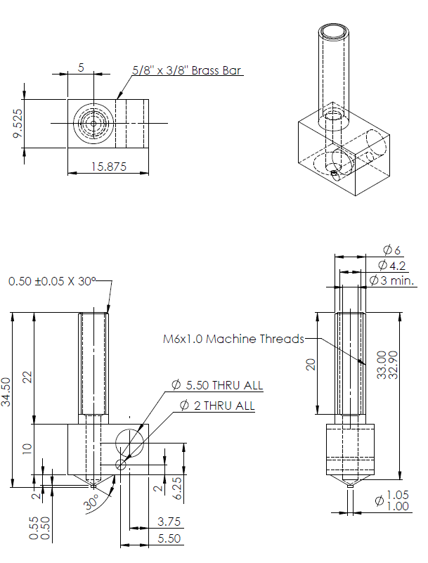
Excuse the poor design work. Funnily enough, metric brass bar is not all that common here in Australia so I proceeded with the initial sizing of 5/8"x3/8" brass bar. Tolerance is to DIN ISO 2768 (fine). So an order was placed at a CNC manufacturer for a small run of these.

It was like xmas when these arrived and I quickly gave the finishing touches on my lathe to test them out. Machining the nozzle tip to 0.5mm and also the Peek insulator.

The PTFE sleeve/tube is standard 4mmOD/3mmID. The loose fit of this tube allows for expansion of both the filament and the tube. I see the direction most people have gone is to cool their insulator to prevent jamming. My personal experience with the loose fit tube has thus far, never produced the jamming effect of the filament. I'm probably one of the lucky ones that have never experienced it. **touch wood


I then increased the shoulder on the Peek insulator to reduce the heat being transferred to the mount. These fender washer can accommodate the 30mm spacing mount. Overall length of the nozzle is 54.5mm with a 40mm insulator.
Here it is mounted to my Prusa...

Initial impressions on the characteristics of the hot end are the heat ramp times are very short compared to my old V2 nozzle. It was able to reach stabilised printing temperature for PLA in  1min30. Extrusion speeds have also increase from before.

Also with the small diameter flat at the end of the nozzle, it'll require some tweaking for the w/t ratio as I found out from the 50% Yoda print.
I was quite pleased with it being the first print from the nozzle. As you probably can tell, the photos are straight from the printer. I will test with smaller diameter nozzles once settings for the 0.5mm nozzle is perfected.